SELF-BALANCING ROTARY INVERTED PENDULUM
PROJECT DESCRIPTION
For a summer project, I designed, modelled, and built a rotary inverted pendulum. An inverted pendulum is an unstable system that relies on a closed-loop control system to self stabilize in the upright position. The system is highly non-linear in nature and is thus difficult to control. I designed the Mechanical Structure using Solidworks CAD then used a combination of machining and 3D printing to build the system. I used Lagrangian Mechanics to obtain the linearized State Space Model, then modelled the closed loop response in MATLAB/Simulink. Once the model was tuned, I implemented the controller on a STM32 Nucleo board with firmware in the FreeRTOS environment. I also wrote two pendulum "Swing-Up" algorithms that allow the pendulum to bring itself from rest to the upright position without user input. The final product was successfully able to swing itself up and balance with 0.2 degrees of pendulum angle variation, and less than 0.5 degrees of arm angle variation at steady state.
Fig. 1: Inverted Pendulum Final Device
DESIGN
The pendulum system consists of the following components:
- 24V, 30W Brushed DC Motor
- 2 x Quadrature Encoder (2048 PPR, one on pendulum and one on motor)
- Machined Aluminum Pendulum
- Machined Steel Rotary Shaft
- 2 x Self Aligning, Low Lriction Ceramic Bearings
- 3D Printed Shaft Housing, Motor Housing
- Aluminum Base Plate
I machined all components myself at the UBC machine shop using the mill, lathe, and waterjet. The first prototype for the shaft assembly consisted of sealed ball bearings which were "sticky" in nature. This added friction caused a small band (roughly 2 degrees) where the pendulum would stay upright even with no control. This resulted in steady state oscillations due to a phenomenon known as "stiction". To compensate for this, I purchased special low friction ceramic bearings which eliminated the issue.
The STM32 board seemed like a good choice for control since it has a high clock speed of 280MHz, 16 bit PWM resolution for motor control, and support for FreeRTOS which allows for scheduling the control tasks with high priority and reducing the importance of tasks such as UART communication for plotting angles. The high clock speed requirement comes from three factors: Extremely high encoder resolution means that interrupt service routines will be running at several kHz. Additionally, I wanted to be able to send encoder data at 100Hz minumum to the host PC via serial in order to log data. Finally, for optimal stability I desired a sampling rate of 1kHz. There are several floating point multiplations / divisions occuring during each controller calculation and there are 2 controllers making this a computationally expensive process. An arduino UNO at 16MHz clock speed is not adequate for the desired level of control.
For operating the pendulum, I designed a C# Windows Forms App for visualizing and logging encoder data, controlling the pendulum, and dynamically adjusting controller parameters. The software completes a handshake via serial with the microcontroller by sending controller parameters (PID) then requesting the current motor / pendulum angles back. This communication happens at a rate of 100hz and the angles are then live plotted and logged to a csv.
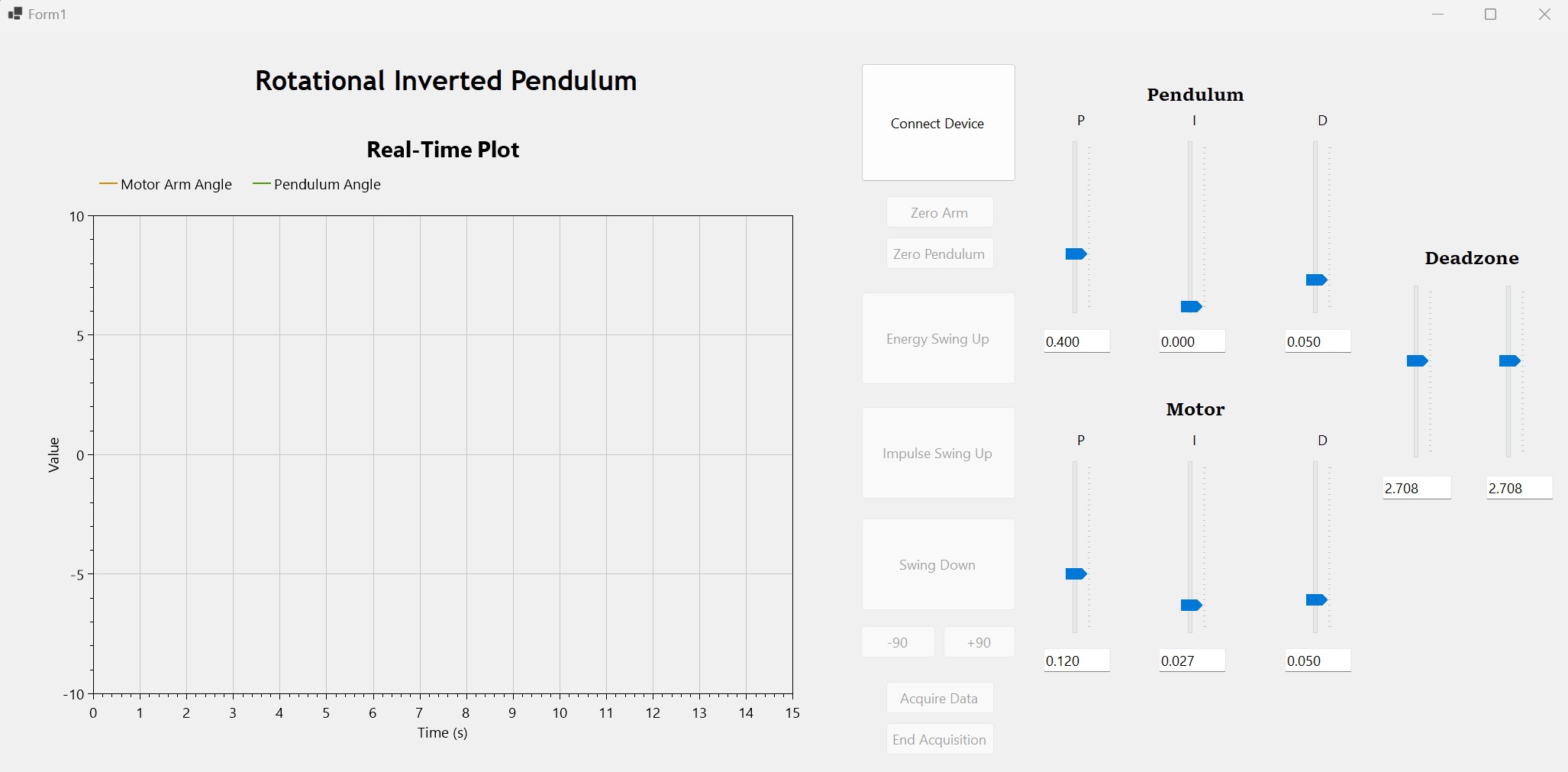
Fig. 2: Inverted Pendulum Windows Forms App
I have made all software and CAD completed for this project open source and available on my GitHub!
MODELLING
After obtaining the state space model and inputting it into MATLAB, I designed a closed-loop control system in Simulink to model the disturbance response. The figure below shows the block diagram.
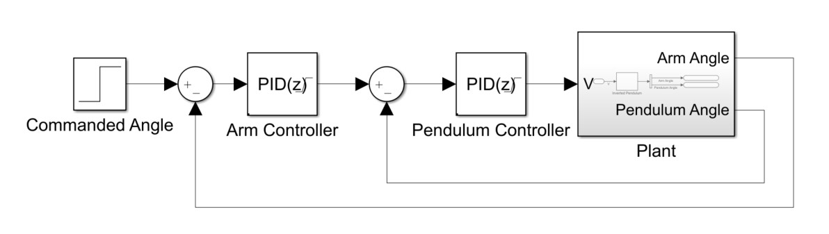
Fig. 3: Balancing Control Block Diagram
The closed loop block diagram includes two discretized PID controllers. The inner controller ensures that the pendulum is moving towards its upright position of zero degrees. The outer PID controller ensures that the motor arm angle trends towards the "Commanded Angle" which is typically hard coded as 0 degrees. This ensures the pendulum is facing forward at steady state. If no encoder and controller is placed on the motor itself, then the pendulum will only balance itself in an idealized case. Due to levelling of the table where the pendulum sits, the motor will have to accelerate in a circle to keep the pendulum balanced. Thus, a second encoder is used to fully close the loop.
The swing-up block diagram is as follows. It is based on the energy equations for the pendulum system and ensures that the motor is helping swing the pendulum up when it is in a positive energy position (sign of the motor voltage is equal to the sign of cos(pendulum angle) x velocity).
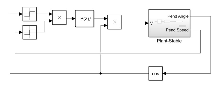
Fig. 4: Swing-Up Control Block Diagram
RESULTS
With the controllers tuned for a smooth and stable disturbance response, I captured the following response:
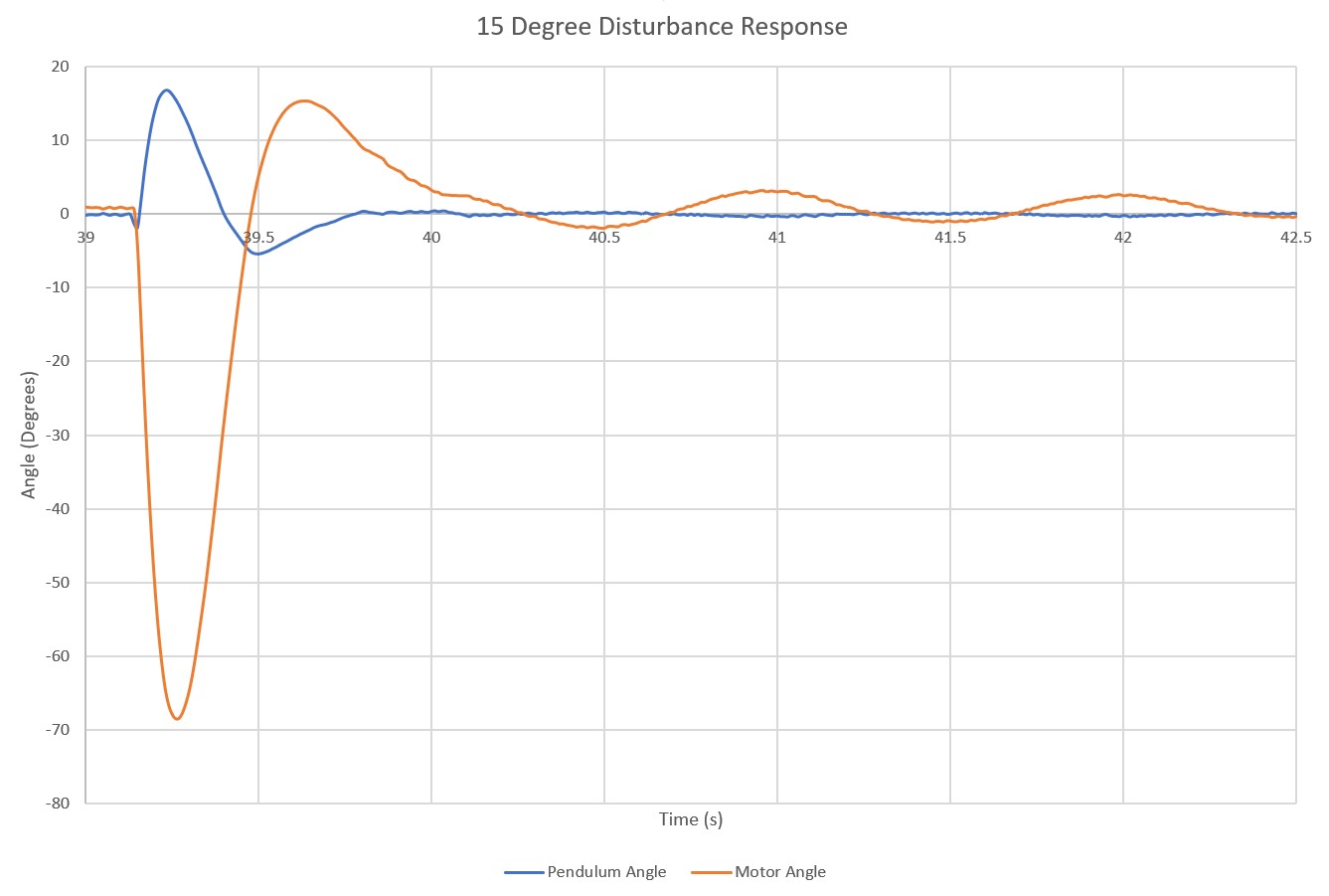
Fig. 5: Disturbance Response
Although this is a stable response, there is a steady state oscillation in the motor with a magnitude of roughly 3 degrees. The oscillation arises from noise in the derivative term of the signal. Adding a low pass filter to the derivative gain reduces oscillations by 80%, but severely reduces the stability of the system to disturbances. To achieve high stability while minimizing the steady state oscillations, I created a dynamic low pass filter. When the pendulum is in its stable upright position at steady state, the filter is enabled which effectively smooths out the derivative term and reduces oscillations. To ensure stability, the control algorithm polls the pendulum angle. If the angle surpasses a threshold (caused by disturbance), the filter is disabled until the pendulum returns to its steady state stable position. The results from this improved control system are shown in the figure below. Steady state oscillations in the arm angle were reduced from +/- 3 degrees to +/- 0.35 degrees.
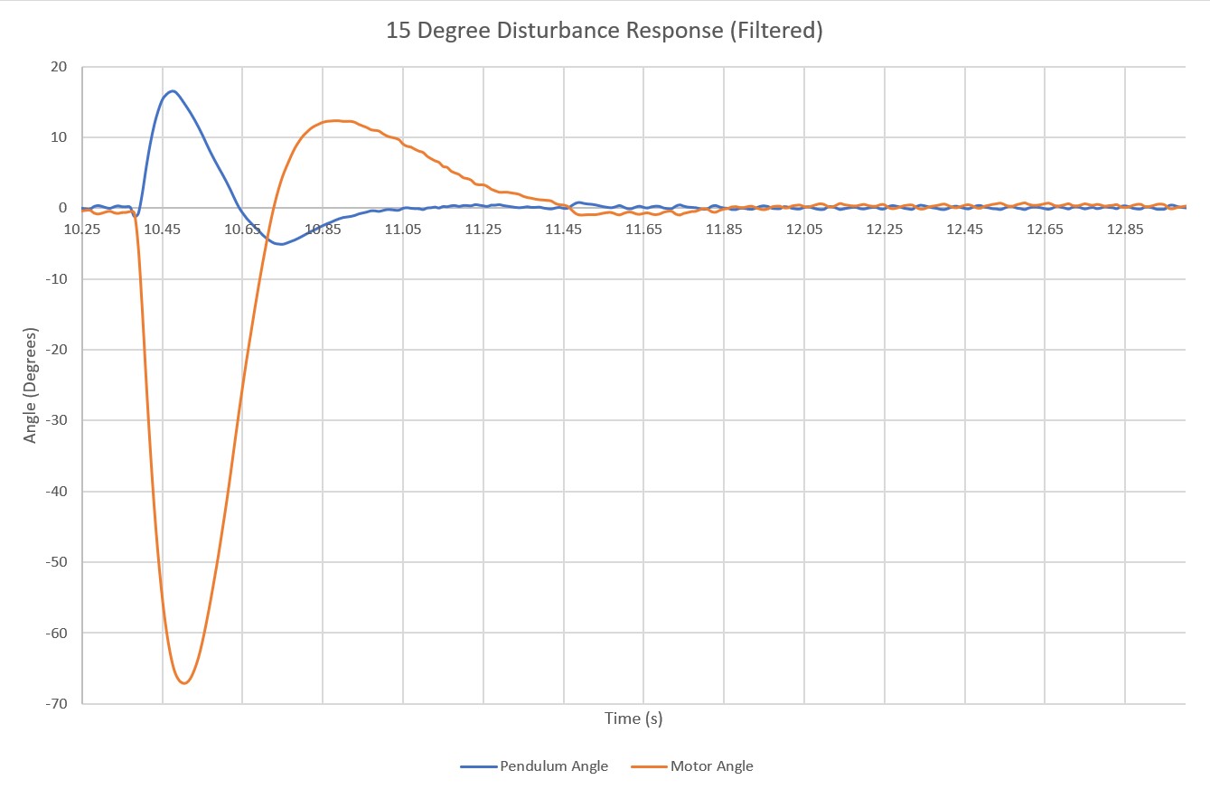
Fig. 6: Disturbance Response (Dynamic Low Pass Filter)
TAKEAWAYS
This project offered valuable lessons in the importance of mechanical assembly quality in achieving optimal system behaviour. The first prototype I made had high friction in the pendulum due to cheap bearings and a slightly imperfect shaft which made a massive difference in the control response. As shown below, the steady state oscillations with the first prototype were almost 20 degrees in the arm angle and 5 degrees in the pendulum.
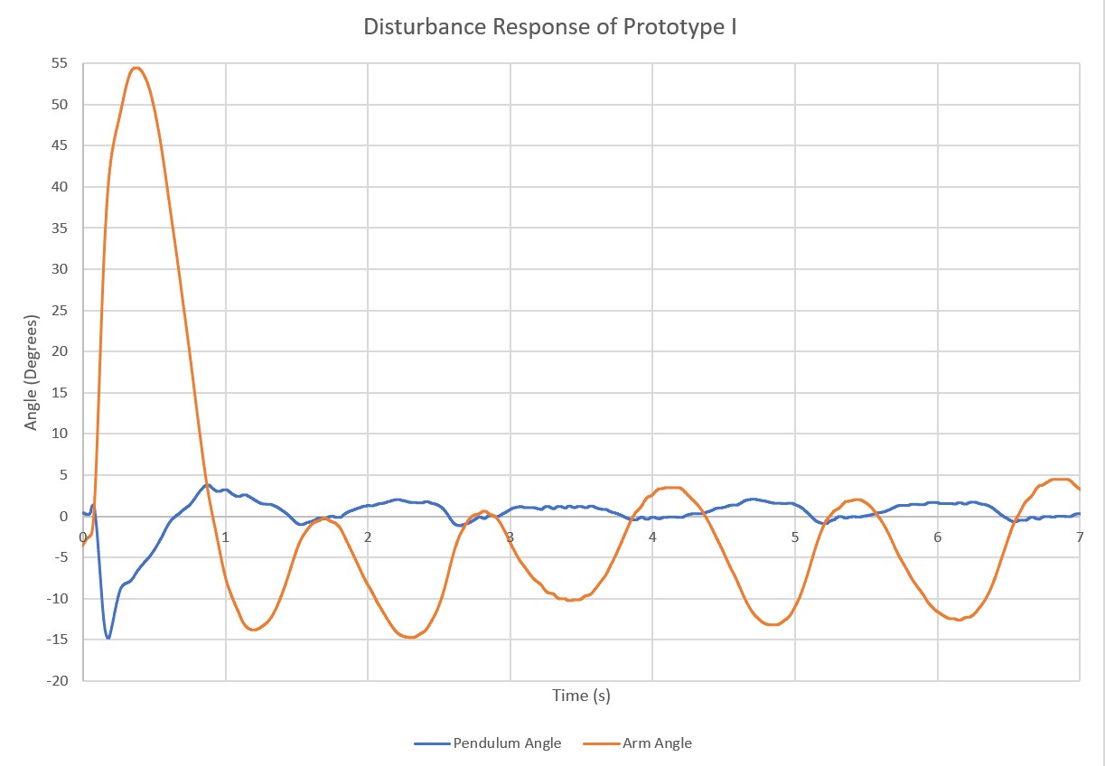
Fig. 7: First Prototype Disturbance Response
Spending more on low friction bearings and machining a custom, precise shaft made a massive difference in the result of this project. It changed a hobbyist project to a professional level product.